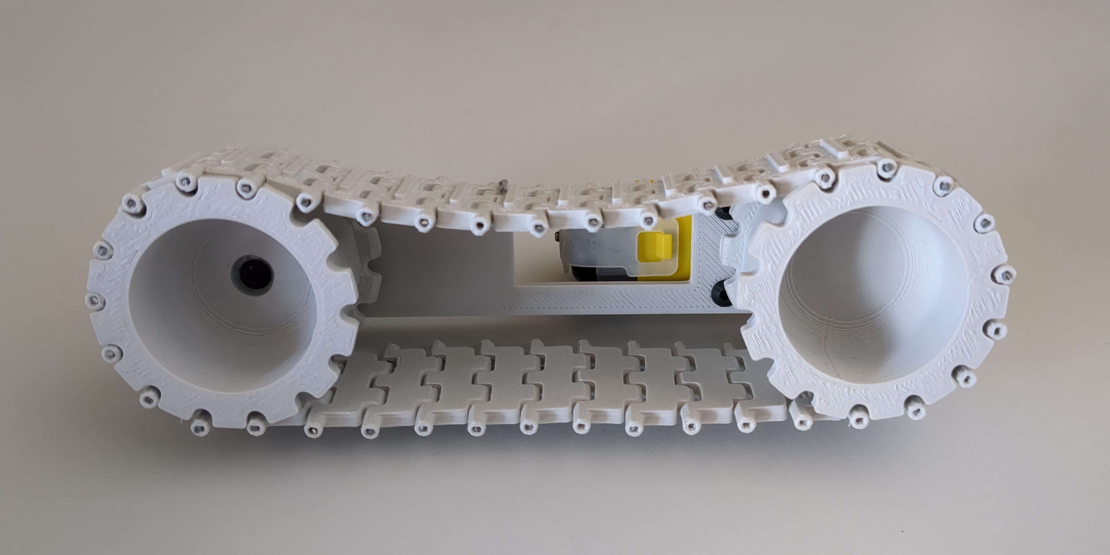
In this post we will look at how we can design our own tracks and 3D print them as a low-cost and made to measure alternative to commercially available options. Tracks on a robot can help distribute the weight across a larger contact area. Along with the ability for the tracks to stretch and deform a bit, this makes the robot able to travel across both softer and rougher terrain.
Designing the tracks
If you look at a set of tracks they might seem complicated, but in reality you only need to design one segment and a way to connect multiple copies together. It is important to note how much distance you want to have between two segments. We call this distance the pitch and it is the most important measurement to make sure the track will fit on a sprocket. In turn, it also determines the minimum diameter of the sprockets and rollers you will need to get the tracks to turn smoothly. If you go for bigger segments, you will end up with bigger sprockets and possibly more ground clearance.
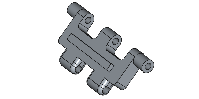
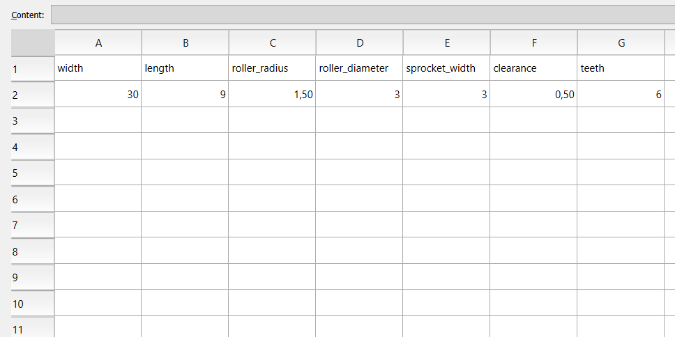
I used the spreadsheet functionality within Freecad to make it easy to change the width and tolerance in my design. It is possible to reference the values in the spreadsheet from the Part Design workbench and have your part update it’s dimensions everytime you make a change to the spreadsheet. For me, this came in handy as I initially designed the segments to have a 1mm clearance everywhere, but this resulted in a very loose track that easily derails. After halving the value for the clearance in the spreadsheet, I could easily export the modified part as an .stl again and print it.
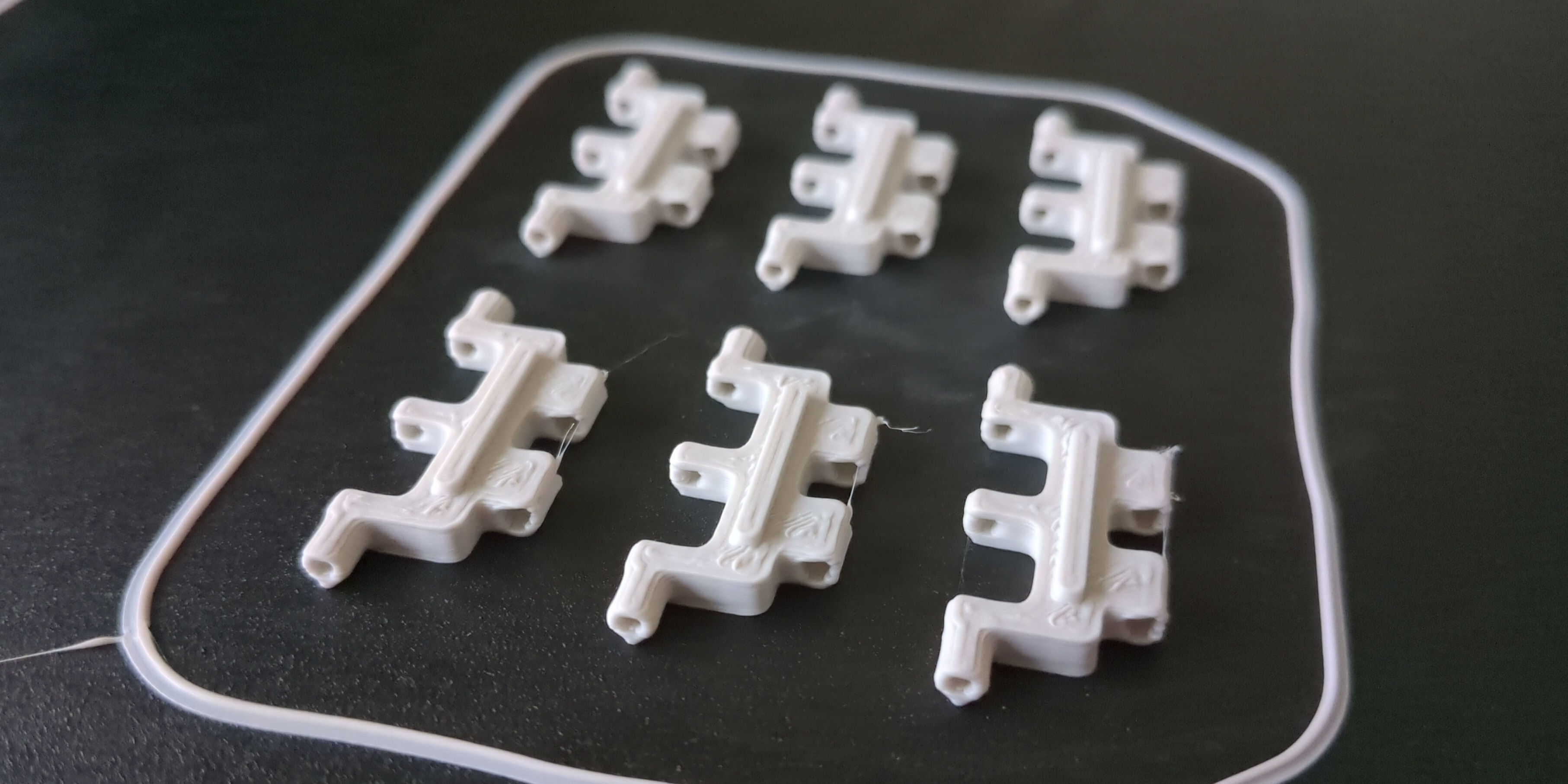
To speed up the printing process, I used the Cura slicer to print a sequence of segments in one go. Since the segments do not have a very large contact area with the print bed, it is possible they pop off. This will ruin your print and the risk increases the more segments you try to print at once. In my case printing 6-12 segments in one go worked best.
Designing the sprocket
To design the sprocket, we start with drawing an N-point polygon with an even number of sides. Having drawn the polygon, we can constrain the length of the sides to the pitch length. We will also draw a circle around the polygon and extrude it. This will be the size of the desired sprocket. We can now create a new sketch and project one of the points of the polygon to draw the groove where the track will sit and create a pocket. Using the polar array, we can duplicate the grooves in a circular pattern to create the final sprocket.
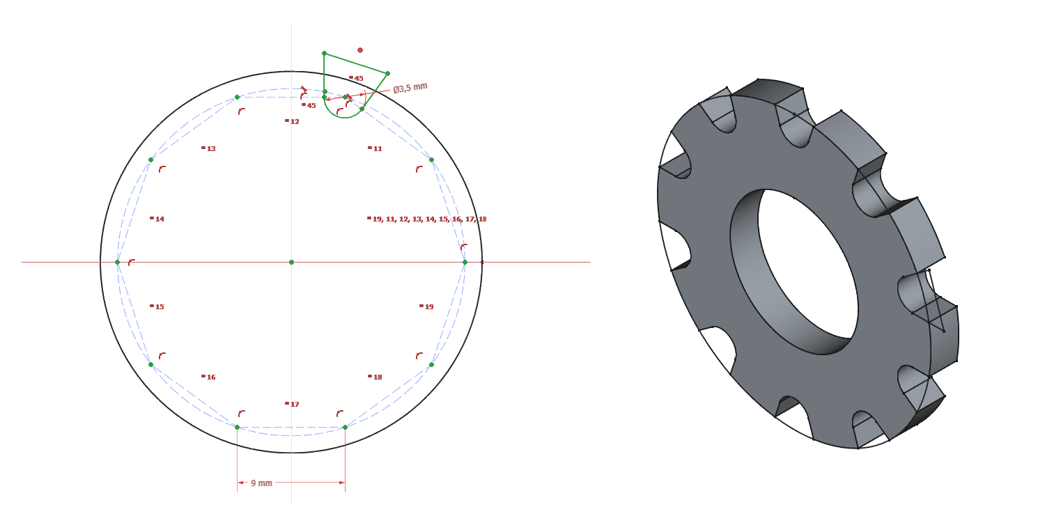
Using the sprocket, it is possible to create a wheel with a sprocket on both sides. You can use this wheel in your design to drive and/or guide your tracks.
Putting it all together
To connect all the track segments together, I used 1mm galvanized steel wire used in gardening. The amount of links you need to connect together depends on the distance between the two sprockets. To cover the distance, you will need at least as many segments as sides of the polygon used to create the sprocket. Then you need to take the distance between the center of the sprockets and divide it by the length of a single segment. By multiplying this number by two and adding the number of sides of the polygon, you get how many segments you will need. If the resulting track is too loose, you can consider adding an additional non-driven guide wheel or removing a link or two.
Closing thoughts
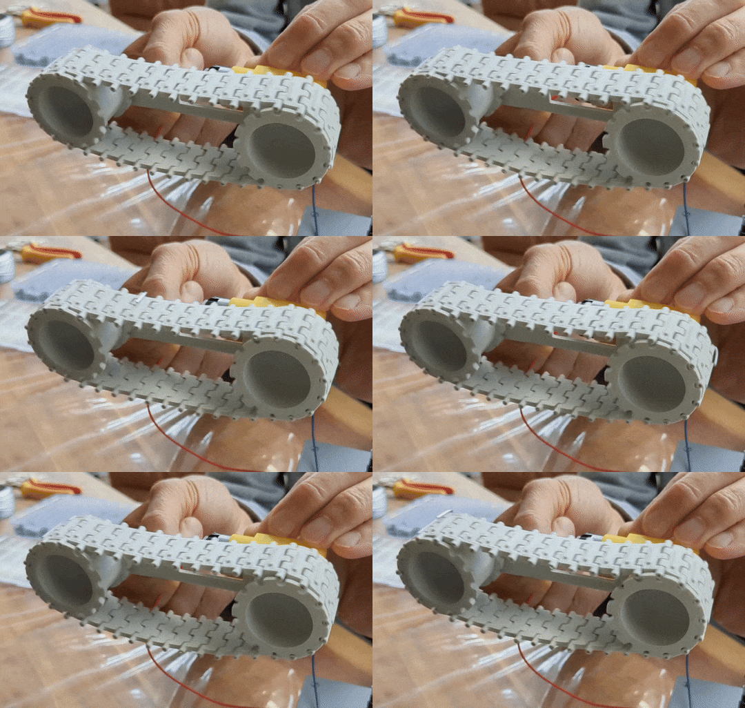
For my demo, I created one driven wheel powered by a yellow TT gear motor. The other wheel is not connected to anything and spins freely. If I decide to create a tracked robot in the future, I would consider increasing the diameter of the sprockets to increase the ground clearance. It would also be beneficial to add some smaller guide sprockets to make sure the track stays aligned well if the distance between the wheels is increased.