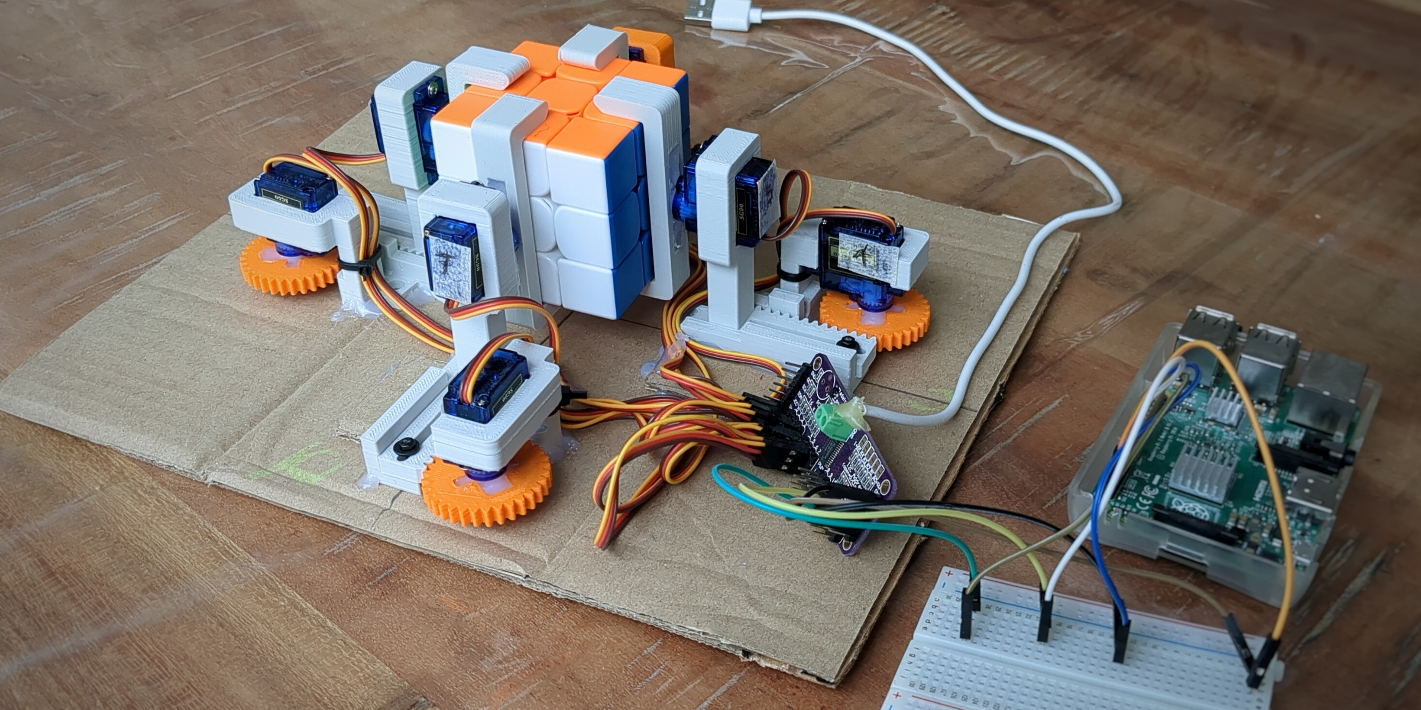
In this post, we look at the process of building a Rubik’s cube solver. It uses affordable parts in combination with 3D printing and is a good beginner to intermediate project in case you want to build something similar.
Project goals
I noticed I have been spending quite a bit of time online looking at projects done by other people. Sometimes this can give you inspiration, but it is also possible to get stuck doomscrolling. So, I decided to pick up a new project that I can build from start to finish in a few days whilst learning more about 3D modeling.
It is important to me to actually finish something. Usually I stop when the interesting parts are done and move on to something new. Not this time, though. To achieve this I will limit the scope and take shortcuts when necessary. There will be no computer vision to recognize the colour of the squares and you will have to enter the scrambled state manually on the command line instead. I also ended up glueing my pieces to a cardboard base instead of screwing them in with the nice countersink holes I designed.
Hardware used
- 1x Raspberry Pi 2B (1GB RAM)
- 1x PCA9685 Servo Driver
- 8x SG90 Analog Servo
- 1x Moyu RS3M Magnetic Speed Cube
For this build I used parts and hardware that I had already laying around. The most expensive part is the Raspberry Pi 2B, but this can also be substituted with a different single-board computer or microcontroller. One good alternative is the Raspberry Pi Zero 2W. It is newer, smaller and cheaper than the full-sized Raspberry Pi 2. During the build, I particularly liked connecting to the Raspberry Pi over wifi using SSH to upload and run new code. When working with microcontrollers and external power sources before, I was always a bit scared to fry a USB port on my laptop trying to flash new software.
When it comes to the SG90 servos, you really do get what you pay for. It is almost impossible to find genuine servos and I’m sure I bought knock-offs of knock-offs. From the lot of 20 I bought, about half of them were dead on arrival. Some didn’t respond at all and others seemed to have the gears glued together. Also, I don’t think the SG90 servos are strong enough to turn an original Rubik’s cube. For this project, I am using a magnetic speed cube which has very low friction to turn the sides and can even be turned when the sides are not perfectly aligned.
Designing and printing the 3D models
Wanting to get better at 3D design and CAD is a big reason why I choose this project. I have very limited prior 3D modeling experience and decided to create all the models in FreeCAD as this is free and open-source software without license restrictions. Earlier in 2024, the 1.0 version of FreeCAD was released which shows how far the project has come. I would consider it quite usable, if not a bit rough around the edges.
The design for the rotating and moving mechanism is the same for all four sides of the cube that will be rotated. In total this results in four different models. One gripper, one moving arm, one base and a gear . If you are interested, the .stl files are present in the github repository. Please take a look at the pictures below to see how they are shaped.
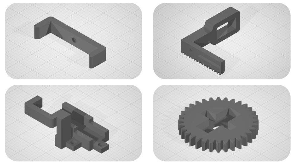
One of the big challenges was to get all the parts to fit correctly. If you design a hole with a 3mm diameter, the hole may not actually be 3mm after 3D printing. The filament is squished out of the nozzle resulting in slightly inaccurate prints. As a rule of thumb, I designed all holes 7% larger than they had to be and this worked out fine. I also measured the sides of the Rubik’s cube for the gripper and scaled this with 7%, but this turned out not so fine. As you may guess, this part was printed way too big.
My favourite thing about 3D printing is the rapid prototyping. I’m using an Ender 3 v3 SE and it levels itself and prints reasonably fast. By designing small parts to check the dimensions, you can get the fit right and then move on to the actual design. I found this saves me some filament and makes me more confident in the final design.
Making the servo motors move
Every servo needs to be connected to a power source and a control signal. The control signal is controlled with Pulse-Width Modulation (PWM) and determines the servo’s position. The PWM signal is a digital signal created by quickly turning on and off a pin. The Raspberry Pi 2B has only two hardware PWM channels, but it is also possible to write software to generate a slightly less accurate signal on any digital output pin.
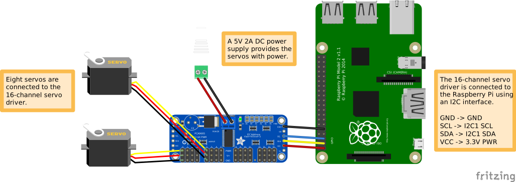
Instead of using software based PWM, we will instead connect an external PCA9685 servo driver. This driver can generate 16 PWM signals and can be connected with our Raspberry Pi using only four wires using the I2C bus. The I2C protocol is a serial communication protocol that connects a master (Raspberry Pi) to multiple slave devices (servos). Every device has it’s own address, so we can send our command to move a specific servo to the bus and all the other listening devices will ignore it.
The Fritzing diagram below shows how to connect the servos, the PCA9685 servo driver and the Raspberry Pi together:
The easiest way to move a servo motor is shown in the following Python snippet. It will rotate a servo motor 90 degrees and back again, like shown in the gif. As we are using a Raspberry Pi running a full Linux operating system, it is possible to use Python instead of C or C++. A Python library to work with the servo driver shield is provided by Adafruit to get us started as quickly as possible. Notice how we initialize the ServoKit with 16 channels, which will give us an array of 16 servos we can individually control. And all that with only four wires connected from the Raspberry Pi to the servo driver!
|
|
The Raspberry Pi is quite fast and would be able to execute the code above without sleep statements, but the servo wouldn’t be able to keep up. If you tell it to rotate and then switch the rotation direction, it would just jerk from one side to the other without ever reaching the desired end position. To prevent this we added some sleep statements, but admittedly this is a flawed solution.
The sleep statements effectively cause the processor to stall. It’s not doing anything and we lose cpu cycles that could have been put to better use. To illustrate this, consider we want to make our program interactive and take an angle from user input. If the user input is only read every 10 seconds because we told the processor to sleep, this makes for a very poor user experience with high latency. Similarly, it would be difficult to move more than one or two servos at a time.
To remove the sleep statements, we can take inspiration from video games. Video games and graphics are usually updated with 30, 60 or even more frames per second (FPS). If you press the left arrow key to move, your character doesn’t just teleport, but usually move smoothly to the left instead. This is exactly the same we want to achieve with our servo motors.
We can create a loop and update our desired servo position every iteration. If you have a specific rotation speed in mind, you can use the time an iteration takes as a delta time and multiply it by the speed to get the distance it should move. After the servo has reached it’s desired position you stop updating it or set the speed to zero. In the video game industry, the time between iterations is also known as the frame time. In case a refresh rate of 60 FPS is targeted, this would result in 0.0167 seconds to compute all the updates. Any slower and you will start to see frame stuttering or ’lag’, and the same is true with our servos.
In the case of my Rubik’s cube solver, however, I don’t really care if there are any sleep statements as I don’t expect any kind of user input. The program will first calculate a solution and then start turning the faces until the cube is solved. If you are fine with a similar approach, you can look at the snippet below. I created a wrapper class that keeps track of the servo position and if it is moving. If it is not moving, we consider it idle or done.
|
|
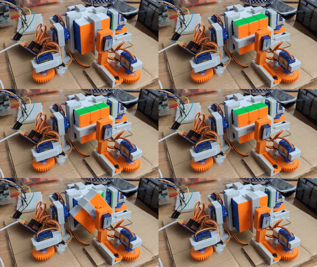
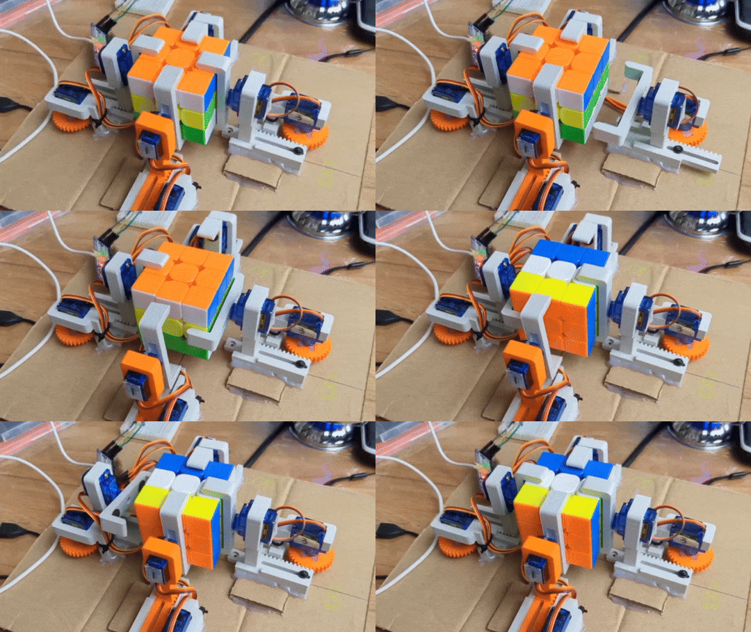
If we write some more of these blocks, we can rotate any servos in any sequence we want in order to solve the cube. Take for example the snippet and gif below. It shows a method used to tilt the cube forwards to be able to rotate the top face. It consists of a sequence of steps. First, we need to ensure the gripper servos are rotated correctly before the tilting operation. To do this, we need to move an arm away from the cube, then rotate it, and then move the arm back in. Then, we can tilt the cube. Finally, we need to ensure the servos are back in the correct starting orientation.
|
|
One last thing I want to mention here is that 90 degrees in the code is not actually 90 degrees in real life. I created a mapping between the physical degrees and the degrees in the code in order to improve the accuracy. My cheap servos are rated for 180°, but the real range of motion is more like 110°. This is also the reason why my Rubik’s cube solver can only rotate a face 90° at a time before it needs to move back the gripper to reset the orientation to rotate the face any further.
Solving Rubik’s cubes
Some might call this cheating, but I used a Python library to get the list of moves needed to solve a given Rubik’s cube. The library uses the beginner’s method to solve the cube and spits out a list of moves like [F (front clockwise), U (up clockwise), R (right clockwise), L’ (left counter-clockwise)]. The Python code just reads through this list, executes the movement and moves on to the next move until the cube is finished. The solution can be found quickly on a Raspberry Pi, but is not optimal. When executing the movements with the harware we built, it can take up to about two minutes to turn all the faces and solve a scrambled cube.
The reason I didn’t write a solver from scratch myself now, is that I have already done it three years ago as part of an university assignment for a course in distributed computing. The solver used Iterative Deepening Search (IDS) to find the smallest number of moves needed to solve a randomly scrambled cube of any size. By dividing the search space over multiple compute nodes in a six-cluster wide-area distributed system, it was possible to study how the algorithm scaled with more compute resources. In an ideal world, we want linear or even superlinear scaling: twice the hardware results in half the execution time. Unfortunately this is not always feasible because of overhead. If you are interested, this is one of the speedup graphs to illustrate how distributed algorithms can scale.
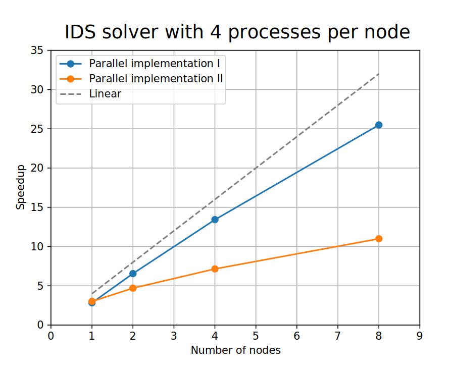
The first implementation (blue) achieves a higher speedup with more processes. In this version, a dedicated master process distributes the work across the other nodes. With a low amount of processes this means the master is mostly idle. The second implementation (orange) also uses a master process to distribute the work, but the master node itself also does some calculations in between. When running with only two processes, the second implementation is faster. But as the number of processes increases, we see the speedup will plateau because the master can not keep up when doing both the solving and coordination.
Closing thoughts
All in all, I consider this project a success. I’m glad I took some shortcuts and managed to finish the project on time and before starting something else. This is my first blog post and I look forward to writing more often to reflect on things I did and things I learned. If you liked it, please share the page with a friend and stay tuned for new posts.